Power Supply Matters
In the documentation for earlier headphone amp designs, I covered power supply selection and related matters as part of the Part Selection Guide. While creating the PIMETA v2 documentation, I realized that this was forcing me to gloss over a lot of details, treating the power supply as if it were no more important than a resistor. That’s just not right. The power supply is the third most significant contributor to the final sound of the amplifier, after the op-amps and buffers. Your control over those chips is pretty limited. You can roll different op-amps and fiddle with bias, but that’s about it.
The power supply, though...you have all kinds of control over that, and there are lots of ways to get it wrong. Therefore, I feel the topic deserves its own section. This gives me the freedom to go into a lot more detail, but even so, I link to more detailed articles from several places in the text below. You should read them, too. This is the power supply we’re talking about here. An amp is all about power. As goes the power supply, so goes the amp.
The Proper Supply Voltage
The PIMETA can run on anything from about 5 to 30 V. The extremes pose some problems, so most people find themselves using something in between. I’ll walk you up through the common voltage options in this range.
The Low-Voltage Ghetto
I set the lowest sane voltage at 5 V as that’s the lower rated limit on the buffers. You may be able to sneak a little below this in some circumstances, but it’s a good practical floor. Getting the amp to function well at this level will be tricky enough. Many op-amps popular for audio need more than 5 V to sound good, and even of those that will run happily on 5 V, it requires a so-called rail-to-rail design to allow it to put out enough voltage to be loud enough with many good headphones.
Bottom line: you can design a good-sounding PIMETA v2 that runs on 5 V, but you’d best have a good reason to push things this hard. If not, you’re needlessly closing off options for better sound.
NiMH 9 V Batteries
The next common step up is especially popular with PIMETAs, that being a single 9 V battery. They have the highest voltage to volume ratio of common battery types. The PIMETA v2 was conceived as a portable amp, and the board was designed with the Serpac H-65-9V in mind, which has a built-in 9 V battery holder.
First, I want to nail down a bit of terminology, because there’s a lot of misuse in casual discussion. A battery is composed of two or more cells. Different battery chemistries have different cell voltages and behaviors. For instance, alkaline batteries are nominally 1.5 V per cell, NiMH 1.2 V per cell, etc. As a child, you may have tried the experiment of stabbing bits of zinc and copper into a lemon and getting a voltage between these electrodes; that’s an electrochemical cell, too, about 2 V nominal. Confusion of the terms battery and cell leads to common errors like AA cells being called batteries. You don’t often see the reverse, batteries being called cells, but it does happen among those who’ve been half-educated about the distinction and haven’t fully grasped it yet. Don’t be that guy.
For the most part, you can talk about the behavior of individual cells and extend that to the behavior of batteries merely by multiplying by the number of cells. There are battery-specific behaviors you don’t see in individual cells, though. This is why it’s important to make careful distinctions between the whole and the parts.
An electrochemical cell’s voltage changes continuously, even when just sitting on a shelf. Think of the number on the label as a “best if used by” rating: it should be put into service or recharged before it’s allowed to self-discharge below this point.
This is the discharge curve for a typical NiMH “9 V” rated for 9.6 V:
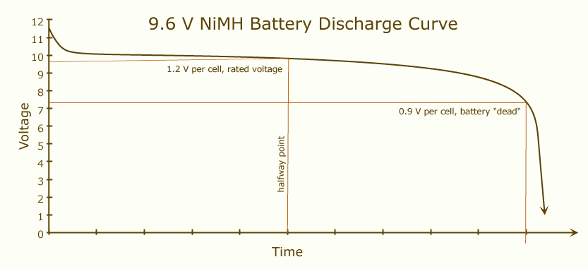
This curve is typical of all NiMH batteries. The vertical scale changes based on the cell voltage and the curve shape changes somewhat depending on the load and qualities of the physical design, but if you commit this typical curve’s shape to memory, you’ll be able to think your way through most battery problems.
There are a number of interesting things you can get from this graph. When fresh off the charger, the battery’s voltage is well above its nominal voltage, often by a few volts. (While actually under charge, it’s even higher, a topic we cover elsewhere.) It drops quickly under load to something closer to its nominal voltage, but never actually hits it until you reach the halfway point in the battery’s useful life. After that point, it continues dropping slowly, though the drop rate increases the closer you get to the end of useful life. Treated properly, a NiMH battery never really “dies” in the sense of getting to 0 V. If you push the cell voltage too low, you risk cell reversal, a very bad thing, so instead we pick an arbitrary ending point somewhere near that knee in the graph so we still get virtually all the available power out of the battery without getting too close to the danger point; 0.9 V per cell is common, but some prefer 1.0 V per cell, for safety.
I tell you all this because it impacts your choice of rail caps. They make 10 V caps, which you might have thought sufficient for a NiMH battery labelled as 9.6 V. Now you know they would probably be damaged; 16 V caps are the right choice in this case. Or, you can switch to an 8.4 V NiMH, which trades one cell for extra capacity in the same volume, plus has the nice property that it probably won’t exceed 10 V when fresh off the charger. That in turn would let you get more rail capacitance than if you had to use 16 V caps. These are called 8-cell and 7-cell NiMH batteries, respectively. (NiMHs are rated at 1.2 V per cell.) They also make 7.2 V 6-cell NiMH “9 V” batteries, which have even higher capacity, all else being equal. More on batteries below.
Wall Power Supply Voltages
If you wanted to go with a wall supply, you can get or make them in the 5-11 V range I’ve discussed so far, but the compactness advantage that makes such low voltages attractive in a portable design don’t apply with wall-powered amps. Even if you will have a hybrid power system, with a wall supply to charge an internal NiMH battery, you will probably still end up with a wall supply of at least 12 V, since you need more than the battery’s peak voltage to fully charge it. (See the section on the NiMH trickle charger for more on this topic.)
12 V
12 V is an interesting supply voltage because there are several popular good-sounding op-amps designed to run on 12 V supplies. They’re not the most popular sorts for audio, but don’t rule them out. This point is also interesting because even the least efficient op-amps common for audio will usually run happily from 12 V in this design. (Many op-amps require more than 12 V to sound good when driving the headphones directly, as in the CMoy Pocket Amp, but the buffers in this design help these chips run on lower supply voltages.)
15 V
Above, I talked about a situation where you might find yourself needing 16 V rail caps. In that case, you might look at common off-the-shelf 15 V wall supplies. I wouldn’t look to this supply level as my first choice, but it certainly can be a good choice.
Higher Voltages
By this point, we’ve gotten past all the danger points for bad sound quality due to insufficient supply voltage. No PIMETA really needs more voltage than we’ve discussed so far. That being said, more voltage can improve sound quality audibly. As a result, many people run amp designs like this right at the upper limit for their op-amps to completely remove supply starvation as a possible source of sound degradation. There’s no free lunch here, though. More supply voltage means using higher voltage tolerances in your rail caps, is less efficient, and can rule out chips you might want to use later. A huge number of good audio op-amps have 30 V supply limits, but 24 V is also becoming a popular op-amp supply voltage design limit, probably because 25 V electrolytic caps are common. Since that’s still far enough in excess of what the amp absolutely needs to run well that it still satisfies the “More Power!!” crowd, this is probably the most popular wall supply voltage for amps of this sort.
I do want to point out that 24 V is merely a convenient value, due to these common design limits on op-amps and electrolytic caps. I frequently find people going through all kinds of contortions to achieve a 24.000 V supply, as if there were some kind of magic there. If you sit down and study it carefully, you might find that your situation actually calls for 22 V, or 27.6 V, or who-knows-what. Don’t be afraid to use an odd supply voltage if that’s what makes the most sense in your situation. Again, PIMETAs are pretty tolerant of voltage variation. There is no single perfect voltage, just a set of interconnected tradeoffs.
I go into more detail on this topic in the companion article Op-Amp Working Voltage Considerations.
Battery Power Supplies
If you’re going to use batteries, there are a few incorrect configurations you need to be sure and avoid.
Unless you leave the buffers out, the PIMETA v2 draws more current than you can efficiently get from alkalines. You can get around this limitation by putting two or more alkaline batteries in parallel, but that’s pretty wasteful. The PIMETA v2 was designed with rechargeable batteries in mind, particularly NiMH types, though NiCd, LiIon and LiPoly can also be made to work. You can’t safely put rechargeables in parallel, but you don’t need to because they can put out far more current than alkalines, without running into efficiency problems. This is because they have lower equivalent series resistance than alkalines, by a few orders of magnitude. A side benefit of this is that the amp should sound better when powered from a NiMH battery than from a paralleled set of alkalines. On top of that, you have the lower long-term cost and environmental benefits of using rechargeables. Win-win-win. (See the section on the NiMH trickle charger for more on this topic.)
One option you have with batteries is to use two in series, calling the midpoint of the pack “ground,” giving a dual supply. I can’t recommend doing this with the PIMETA because there’s nothing in this circuit that prevents one side of the supply from draining faster than the other. If that happens, when one side depletes far enough, the output DC offset of the amp can rise high enough to damage headphones. If you had some external circuit that would reliably cut off power when one side of the battery got too low, you could avoid this problem, but I’ve played with such things and found them not worth the bother. I recommend you keep things simple and just put all the cells in series.
The PIMETA circuit board has special support for dual batteries in series. We went to the trouble because 2×9 V is a fairly common configuration. Also, the largest AA and AAA cell holders only take 6 or 8 cells, not as many as we’d like in a lot of cases, so we often want to take two of these battery holders and put them in series to get a higher supply voltage. The BATT connector on the PIMETA v2 circuit board has four positions. The outer two pins are for the positive and negative connections to the amp circuit, and the middle pair are simply connected together. Therefore, if you run the two wires from one battery holder to the + pad in the BATT group and to the pad next to that, and the other battery holder’s wires to the - pad and the pad next to it, the batteries are then connected in series. This avoids the hassle of connecting the two battery holders off-board.
I have more to say about batteries below, but first we need to cover wall supplies.
Wall Power Supplies
You can’t just use any random wall supply with a PIMETA. Not only are some types better than others, some simply won’t work right with this circuit. The two things you need to pay attention to are regulation and isolation.
Regulation
An unregulated power supply’s output voltage will fluctuate as the wall voltage fluctuates. Also, unregulated power supplies tend to be cheap all around, so they’ll have a lot of noise and ripple on their outputs. There’s not a useful distinction between noise and ripple for our purposes here, so we’ll just call it all “noise:” stuff we don’t want.
The low-speed rail caps, the high-speed rail caps and the bypass caps will filter some of this noise out. The op-amps and buffers will actively reject some of it, too, particularly lower-frequency noise. If the power supply is putting out enough noise, however, enough can get past these circuit elements into the amp’s output to be audible. The quieter the supply, the less risk of noise polluting the amp’s sound. Regulation is a good first line of defense against noise, leaving less for the caps and chips to deal with. There is no such thing as perfect regulation, but you can get awfully good regulation. I go into some detail on this topic in the companion article, Op-Amp Power Supply Quality Considerations.
The most common sort of regulated power supply is the switching power supply. Although there’s nothing conceptually wrong with switching regulation, low-quality switchers can put more audible noise into the output of the amp even than an unregulated supply, because of the way they work. High-quality switchers are readily available, but even the best of these is not actually desirable for audio. The main benefits of switching regulation are small size and high efficiency, which is why they’re so common. Also, some switchers will work on any power system in the world, simply by changing the power plug. Not all switchers offer this feature, but it’s a dead giveaway. If you have a power supply that says it will accept anything like 90 to 260 V, you can be certain it’s a switcher.
The better type of regulation for audio is linear regulation. It’s less efficient than switching regulation, and if it supports multiple world power systems at all, you typically need to flip a switch or mess with jumpers to make this change. We like linears for audio despite these weaknesses because it’s easier to achieve low noise with a linear design. If you’re looking at a “regulated” supply that doesn’t say whether it’s switching or linear regulated, it’s safe to assume it’s a switcher. Makers of linear-regulated supplies always trumpet this fact because of the associated virtues.
Isolation
A wall power supply also needs to be isolated to work properly with the PIMETA except in some fairly uncommon special cases.
Isolation means that none of the output (DC-side) leads are directly connected to any of the input (AC- or wall-side) leads. It’s common in commercial power supplies to tie the negative DC output pin to earth ground or neutral on the AC side. This can be good for safety or noise reasons, but it can cause a problem with the PIMETA’s virtual ground scheme.
You can get away with powering a PIMETA from a non-isolated supply if you only use it with a battery-powered source, and only to drive headphones. This is because the source and the “sink” — your headphones — are isolated, so the amp doesn’t have to be. What are the chances of that, though? If you’re using the PIMETA with a wall supply, chances are that your source is running from a wall supply, too, and there’s a good chance it isn’t isolated itself, or is connected through the ground shield in the audio cables to something that isn’t isolated. Maybe you’re using the PIMETA as a preamp, rather than to drive headphones, so the sink is another wall-powered component, opening the same risks of non-isolation on that side of the amp, too. In any of these scenarios, the PIMETA will pick a fight with Planet Earth, and it will certainly lose that fight. The least that will happen is that the sound will be terrible because the virtual ground has collapsed, causing massive clipping. You can damage headphones, speakers, and the ground channel this way, too.
Isolation allows the amp’s virtual ground to “float” to whatever level is required by the other components in the audio chain. Batteries are inherently isolated, being self-contained power sources. Linear-regulated and unregulated supplies get isolation for free due to the galvanic isolation of the transformer. (It’s fairly common to trade away this isolation for reasons covered below, but the important thing here is that you have to start with isolation to be able to profit from the trade.) Achieving galvanic isolation in a switcher requires intentional design, which is why it’s rare to see. If they went to the bother, you can be sure they’ll mention this in the datasheet, probably on the first page.
It’s easy to test a power supply to find out if it’s isolated. Using an ohmmeter or continuity meter, check for continuity between AC neutral and DC V-. If the supply has an earth ground connection, check for continuity between that and DC V-, too. If you get low resistance — continuity — it’s non-isolated and thus is no good for a PIMETA except in special cases. If you find no connection between AC neutral or earth ground and the negative output pin, check all the other combinations, too. It’s less common to see a non-isolated supply be so through one of these other paths, but possible.
Another special case where you can get away with using a non-isolated supply with a PIMETA is if you’re only using it to power the NiMH trickle charger, and then only while there are no audio cables plugged into the amp.
The DIY Approach
You may want — or need — to make your own linear-regulated wall power supply. I no longer offer linear power supply circuit boards, but there are several straightforward power supply designs already available. One option is to build something based on a linear regulator IC, like the LM317 or 78xx family. My old TREAD design was one such, and the information on those pages may still be of some help to you.
The safest way to build power supplies of that sort is to build only the DC regulator part yourself, and use a cheap unregulated wall wart to do the dangerous high-voltage AC to low-voltage DC conversion.
For instance, consider the LM7824 regulator. You can use just the bare IC, with no other external components, or you can add a few external capacitors to get better performance. You simply put it inline between an unregulated DC power supply and load’s power input. See its datasheet (linked above) for more details.
As with anything else in audiophile land, there’s no real limit on how crazy you can get with your power supply design. It’s possible to spend hundreds of dollars on this, if you want.
Both Battery and Wall Supply
It’s quite possible to configure your PIMETA to run from both a wall power supply and from a battery. This is actually a highly recommended configuration for a portable amp, as the PIMETA v2 was designed with NiMH rechargeable batteries in mind.
Rather than make you remove the battery from the amp to recharge it, we built a simple NiMH trickle charger into the circuit. When you connect the wall supply, it both powers the amp and trickle-charges the batteries. Turn off the wall supply or unplug it, and the batteries instantly take over again.
Click the link above for more on this feature.
Battery Supply Run Time
As you’ve gathered from the above coverage of batteries, there’s nothing simple about battery power. That’s why the simple question, “How long will it run on battery power?” has no simple answer.
The most accurate way to answer the question is to just build the amp, put a freshly-charged battery in it, turn it on, and listen to it until it dies. If you have to know before you start building, or you’re trying to decide if the observed performance is correct, the best you can do is work out a rough estimate based on the battery characteristics and the amp design. Then you still have to build it, test it, and compare the results to the estimate. If the actual behavior is within about 10% of your estimate, don’t worry about the difference.
If your estimate doesn’t match up with actual behavior, it could be for any of several reasons. Perhaps the amp is marginally stable so it oscillates under some conditions but not others, drawing more current than it should. Perhaps your batteries are worn out, so they can no longer deliver the performance quoted on the label. Perhaps you have left something out of the estimate, or made some other error in calculation.
Batteries are measured in amp-hours, or for the sort of batteries you’re likely to use for a PIMETA v2, milliamp-hours. In principle, then, you can then divide the milliamps the PIMETA v2 draws into the mAh rating for the battery and get hours of run time. For instance, if we had a 600 mAh battery and the amp draws 60 mA, the battery should last 10 hours.
Since you can probably read the mAh rating of the battery right off its side, the obvious question is, how much current does your particular amp draw? Well, this is DIY, so there is no standard configuration, and thus no standard current draw. At best, we can talk about the “least surprising” configuration. That’s where my 60 mA current draw number comes from above. Your PIMETA v2 could draw significantly more or less than this, however. To get the right answer, ideally you measure it, but that requires building the amp and finalizing its configuration first. You can try to calculate it instead, but beware that it’s easy to overlook something when doing that.
The above discussion works on the assumption that the amp’s quiescent current draw — that is, what the circuit draws when just sitting there idle — is essentially the same as its draw under load. This is true for the PIMETA because it’s a pretty inefficient circuit. By far, most of the power that goes into it is turned into heat, not sent to power the headphones. The difference should be less than 10%, so that’s your maximum error, all else being equal.
All else is not equal, of course. The methods above assume the battery isn’t worn out, that the amp’s current draw doesn’t change sharply at some point in its run time (as can happen with a marginally stable amp), and that the mAh rating on the battery actually applies at the current draw you’re pulling from it.
That last point is important: the mAh rating system has a built-in assumption, that amps times hours equals a constant value. This is simply not true. For it to be true, batteries would have to be ideal linear power sources. Nothing is ideal. In batteries, the main nonideality we have to deal with is that as current draw goes up, the mAh rating of the battery effectively goes down. This is one way of looking at the “no alkalines” rule above: an alkaline 9 V 600 mAh battery will power a 60 mA PIMETA for a time, but you won’t get the 10 hours out of it that the mAh rating implies. There are actually two reasons for that. One I already covered: alkalines aren’t intended to supply such high constant currents, so their mAh rating is taken at a much lower current, so the numbers come out larger. The other has to do with matters covered in a separate article, Op-Amp Working Voltage Considerations.
Single-Voltage or Dual-Voltage Power Supply?
The discussion above assumes you will be using a single-voltage power supply; that is, power supplies with just a positive and a negative output terminal. That’s the sort we had in mind when designing the PIMETA. These are simpler and less expensive than the dual supplies traditionally used with audio equipment. We get that benefit with IC2, the TLE2426 “rail splitter.” It splits the single supply voltage in half, which we tie to the PIMETA’s ground plane, creating a type of virtual ground. (We also call this IG, for “input ground,” to distinguish it from the output ground connection to the headphones, OG.) Thus, a 24 V supply is effectively turned into a ±12 V supply.
(See the companion article, Virtual Ground Circuits for a more thorough discussion of this topic, including more ways to create virtual grounds. The PIMETA circuit is down at the bottom of that article.)
If you leave IC2 out, you can instead use a genuine dual voltage power supply, with 3 output terminals. You run + and - to the board just as you would for a single-voltage supply, and you run ground to one of the IG pads in the scratchpad area.
Why do this? Well for one, maybe you happen to have a dual supply sitting around, and don’t want to install IC2 on the board and leave the ground connection of your power supply out. There’s nothing really wrong with using IC2 in this situation, it just seems wasteful. Or, maybe you just don’t like virtual ground schemes, and so prefer to use a true dual supply. You could avoid the need for an isolated supply that way. Whatever your reason, the PIMETA v2 will accommodate a dual supply without difficulty.
Choosing the Right DC Power Input Jack
The most common sort of DC power jack is the barrel jack. They’re durable, and they keep the V+ power connection safely shielded away on the inside of the plug. (Well, typically, anyway. Sony likes to reverse this in wall warts for their portable players, just to be bloody-minded, I think.) They come in many sizes, with the outer and inner diameters given in millimeters. Except when my choice of power supply forces me to use a given size, I prefer to use the largest common type, 5.5/2.5 mm. The large inner pin is durable and lower in resistance than with a smaller connector.
If your amp will be wall-powered and your enclosure is metal, the DC input jack should have a plastic body. This is confusingly called an isolated jack, but is not the same thing as an isolated power supply. It just preserves the supply’s isolation from the rest of the world by preventing any connection between the power supply and the enclosure.
Metal-bodied DC jacks are far more common than isolated ones. Since the outer connector is usually used for V- with barrel connectors, and the jack ties the outer part of the barrel to the jack shell, using such a jack with a metal enclosure means you tie V- to the enclosure. This isn’t necessarily a bad thing, but it does mean you have to be careful to isolate the input jacks and the pot shell from the enclosure, else V- gets tied to IG through the enclosure, starting a fight like the sort described above, only entirely within the amp.
If your enclosure is plastic or wood, there’s no reason to avoid metal-bodied DC jacks.
System-Level Design
We’ve touched on a lot of topics above, but we haven’t really tied it all together. Your PIMETA is going to be just one of several different circuits connected together: source, DAC, preamp, headphone amp, power supplies for each... This collection of components needs to work together as a system. It doesn’t matter how well the PIMETA alone works, if connecting it into the system breaks the system.
Ever notice how many words technical people use for “non-functional”? (Broke, scrogged, roached, toast, fried, hosed, glitched, fuc*^&%....) That’s because there are lots of ways for it to happen, and it helps to have a funny term handy as a psychological relief valve when the circuit you spent all that time building refuses to work. Particularly with DIY, it’s fairly common to have a collection of components that each work fine individually, or in certain combinations, but not all together. Calling your electronics names is better in the short term than smashing them in frustration, but ultimately you want to find out what went wrong and fix it. Or better, learn to avoid problems in the first place. That’s what we’ll try to do in this section.
Why cover it here? Because systems failures usually come down to power or ground issues. Much has been written on the topic of preventing damage to the audio signal within a given circuit. All of that is for nothing if you have a power or ground incompatibility that wrecks the sound as it tries to get from one circuit to another.
The most common error is using a metal case and having an electrical connection conflict among the panel components. Many panel components have metal shells or bushings which can thereby tie something in the PIMETA circuit to the case. You can only have one of the various power rails and grounds connected to the case. You will have a problem if you try to connect IG and OG together through the case. Another common conflict is V- and IG.
There are a number of ways around this trap. One is to use a plastic or wooden case. Another is to use isolated jacks, which either have plastic shells, or simply don’t have any electrical connections from the component workings to their metal shells. The discussion above about isolated power supplies and batteries is also relevant.
You want to connect a metal case to either IG or V-, else it’s not acting as a shield, in which case you might as well not use metal at all.
The easiest way to connect the case to V- is to use an uninsulated DC barrel jack with a tip-positve DC supply. That then means you have to use insulated input and output jacks, and you can’t do the pot ground strap trick with the PG pad on the board to quiet humming when you touch the knob. The V- supply tie might fix pot humming, but not often, in my experience.
Connecting the case to IG has a much better likelihood of giving good audio performance, not just good electical behavior. You can connect the case to IG via the pot ground strap, the input jacks, or both. Then you need a isolated DC input jack and an isolated output jack.
This space intentionally left blank. :)