DIY Heat Sinks
In a recent thread on Head-Fi, someone asked how well a paperclip would work for heat-sinking a TO-220 part. Much speculation ensued (much of it from your humble author), including opinions that a penny might work better, and then the argument moved on to exactly how to use the penny and so on. I eventually decided that experimentation was called for, which lead to this article.
Test Setup
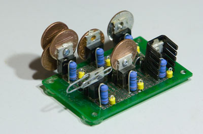
I configured six LM317s as 0.125 A current sources propped up by silicon diodes. The diodes are remnants of a discarded idea, so their only purpose in this version of the test was as a place to clip the negative-side power lead. I then attached different heat sinks to each current source, put approximately 18 V across each one in turn, and recorded their temperature over time.
|
Results
From left to right, front to back, the configurations and results are:
|
“Configuration 0” is the first one with the paperclip taken off. It was easy enough to switch between these that I didn’t bother to make a separate instance for the naked regulator on the board.
See below for the reason the current and voltage in each test was different.
You can see more details and pretty graphs in the results PDF (2.8 MB). The raw data is available here (576 KB, ZIP format) along with the Mathematica notebooks used to generate the PDF.
Discussion
1: Surprisingly, the paperclip does better than adding a lone penny, regardless of how you attach the penny. This is probably because it puts more of the "heat sink" surface out in the air away from the regulator, and it doesn’t occlude so much of the regulator’s radiating surface. Note, however, that it’s not greatly effective. It’s good for maybe 5°C/W, no more.
2: #4’s little brother, and it doesn’t work nearly as well. In the earlier version of this test (reported in the Head-Fi thread), it came out much closer to #4’s performance, but the test was flawed and the load was lower. Either alone could explain the difference, or it could be some combination.
3: Bog standard heat sink. Available lots of places, works well, and will probably cost you less than what it’s protecting. Standard lore says parts will last twice as long for every 10° C drop, so the regulator should last four times as long in this test. Regardless of the actual numbers, it’ll pay for itself unless you’re using some extremely cheap parts.
4: This is four pennies bolted together in a fan configuration. As you can see, it did slightly better than the Aavid heat sink. It also takes more room and is harder to put together, so I can only recommend it if you need something ASAP and getting a “real” heat sink will take too much time. In a previous version of this test, the penny closest to the regulator was oriented 180° from how you see it in the picture above, to maximize contact between the penny and the regulator. I also had the second through fourth pennies aligned together. In that test, the Aavid came out slightly ahead, so fanning the pennies and reorienting the first one helped, but not much.
5: We’re giving up about 5 degrees in this test by using epoxy instead of heat sink compound. This penalty should scale linearly with the load: if you double the load, you should expect the penalty to be right around 10 degrees.
6: Soldering the penny actually gave a higher temperature than using heat sink compound in this test, but that difference is probaby within the margin of error. In the previous iteration of these tests, there was also one degree of difference, the other way around. I think the main lesson here is that it isn’t worth the effort it takes. Just use good heat sink compound and bolt it tightly, and you’ll get nearly all the benefit.
Test Details
The regulators are all Fairchild LM317Ts. They’re probably even from the same tube.
I used an adjustable bench supply to put approximately 18 V across the regulator under test. I found that the initial current through the regulator would be slightly lower at the start, and would rise by about a milliamp as the parts heated up. After the current level stabilized, I measured the voltage across the regulator and current-setting resistor, then adjusted the power supply voltage to put exactly 2 W through the regulator. This factored out the component tolerance differences from the test. You can see the different voltages and currents in the results table above. The voltages are those across the entire circuit, so it does include the varying diode voltage drop. You can directly calculate the voltage across just the regulator circuit using the formula V=P/I, where P is 2, and I is in the table above.
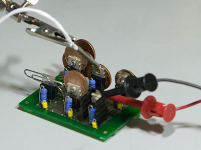
The measurements were taken with an Agilent 34410A DMM, using a 5 kΩ thermistor. The thermistor was held by a “helping hands” a short way up the insulated cable from the sense tip. I placed a small bead of silver-bearing heat sink compound on the top center of the regulator’s tab, then used the helping hands-weighted thermistor like a turntable stylus, dropping the tip right in the middle of the heat sink compound. I chose this point to measure from as it’s the only common point I could get to on all six regulators. A point closer to the IC package would have given a higher temperature, but it was more important to get comparable measurements than to get exact die temperatures.
|
| Test setup re-creation |
I did tests 1-6 on a mild night in early October with the heat turned off in the house. All of the electronics in the test room were either off, or were the sort to put out a constant heat level. I put a box between the DMM and power supply and the test circuit, to prevent their cooling fan exhaust from directly blowing across the test area. Therefore, there is only one trend in the ambient temperature around the regulators, that being the natural slow nighttime temperature drop. It being one of the summery nights we often get here in the fall, the temperature did not drop very much through most of the tests. You can see the most pronounced drop in the downward trend in the raw data for the first test, as this one was started right before sunset.
After I started each regulator cooking, I left the room, closed the door, and let it sit until the temperature to reached equilibrium. The Agilent 34410A is an LXI instrument, so I was able to watch the temperature change from the other room. Once it seemed to settle in a stable temperature range, I told the meter to start gathering data, 10,000 readings at 3 per second. At the end of the test, I popped the data into Mathematica and ran some tests on it. It was clear from the histogram in a few cases that the regulator jumped into a new equilibrium after I started the test, as you’d see a two-peaked distribution. (Test #3 still shows a little of this, but since it’s a supporting test, and not the main object of this exercise, I let it slide.) If I saw a two-peaked distribution in the histogram or a jump in the list plot, I restarted the test immediately. Since each test ran for nearly an hour, I felt confident that if there were no such artifacts, that the regulator had settled into a nicely stable state.
The temperatures quoted above are the median values from the Mathematica data analysis. You may want to study the results more closely to get a more nuanced picture.
All of the pennies are 1981 or earlier vintage, that being the last year US pennies were made mostly of copper. After that, they’re mostly zinc, with some copper plating. The pennies in configurations 2, 5, and 6 are all 1981 pennies made in the same mint. I didn’t feel a great need to find identical pennies for configuration 4.
In configuration 1, there’s nothing added between the heat sink and the regulator. In configurations 2, 3 and 4, I used a no-name silver-bearing heat sink compound. (The same stuff that was used on the thermistor.) In configuration 5, it’s a fast-curing epoxy. In configuration 6, it’s 62/36/2 solder.
In all penny heat sink configurations, the surface towards the regulator is the reverse side, as it looks like the obverse has more relief. Also, Miss Manners says it’s not nice to apply sticky substances to ex-Presidents’ faces. (Miss Manners has nothing to say on the topic of power tools, so I’m also in the clear with configurations 2 and 4.)
All pennies were cleaned in an acid bath to remove dirt and corrosion. I used CLR initially, but switched to a vinegar and salt solution that was recommended on a coin collector’s site. I flushed the acid off thoroughly with tap water.
Holes drilled through the pennies are the same size as the holes through the Aavid heat sink and the regulators’ tabs. I used small #2 bolts, trimmed so nothing sticks out beyond the nut, to minimize their contrubution to the thermal bulk. Normally you’d use a #6 or #8 bolt and proably wouldn’t clip the extra length off, so that would help lower the temperature a bit more.
The soldered penny was first sanded down and lapped using 400 and 600 grit wet/dry sand paper to remove the coin’s reverse relief, and thus provide a more direct contact between the IC tab and the coin.
This space intentionally left blank. :)