Modified Linkwitz Crossfeed
There are several different publically-available crossfeed circuits. They all sound different, they have different levels of complexity, and some make demands on the circuits they’re used with. I’ve settled on Chu Moy’s Modified Linkwitz Crossfeed for amps I build due to its low complexity, good sound, and low requirements on the surrounding circuit.
I was happy enough with this circuit that I made PCBs for it and offered them in my shop for years. Due to dropping demand, I can no longer make PCBs for this project economically. Sorry. For those who are interested, here are the EAGLE files for the project: ZIP, 28 KB
This circuit is simple enough that a PCB is a fairly minor convenience. It wouldn’t be difficult to build it up on perfboard.
|
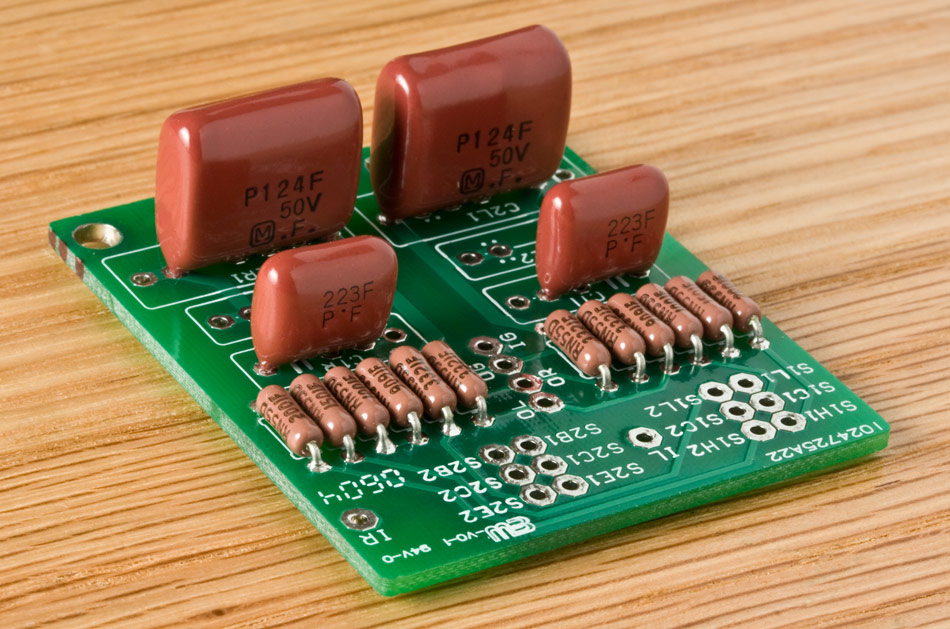
A populated Modified Linkwitz Crossfeed PCB (v1.2)
I won’t go into much detail about this circuit, since Chu Moy’s article has all the info you need if you want to tweak the circuit. I do have a version of the schematic here.
Parts
The circuit uses four capacitors and 10-12 resistors, depending on whether you want single-level crossfeed or a high and low crossfeed setting.
In Chu Moy’s article, he describes two different sets of part values, one for a low-impedance (“low-Z”) version of the circuit, and one for a high-Z version. I prefer the high-Z version because I think the crossfeed circuit works better between a source and a headphone amplifier. The low-Z version is for use directly ahead of the headphones, a poor place for a crossfeed circuit, in my opinion. A bonus of using the high-Z version of the circuit is that its capacitor values are lower, allowing higher quality capacitor types to be used. If you really wanted try the low-Z version of the circuit, you would need to compromise on capacitor quality, since more compact capacitors generally sound worse. I will use the high-Z values exclusively below.
Not all capacitor lines have 0.12 µF capacitors in them, but you can count on finding 0.1 µF and 0.022 µF; paralleling them gets you 0.12 µF total. Since C1 is 0.022 µF, you need caps of that value anyway.
(0.1 µF plus 0.022 µF is not 0.122 µF unless you’re dealing with 1% caps, due to accuracy limits. Besides which, a cap line claiming to offer 1% tolerance should have a 0.12 µF unit.)
The best sort of caps for this application are polypropylene film-and-foil. The best widely-available polypropylene film-and-foil cap line is the Orange Drop 715P series. These are very large caps for their capcity, so you might want to look into something more compact. Panasonic used to offer the ECQP line, which was a great compromise between quality and compactness, but they have discontinued them. My next best suggestion would be Wima’s FKP series.
If you’re willing to step a bit down the quality curve, metalized polypropylene caps are much more widely available, and more compact than equivalent film-and-foil varieties besides. Both Wima’s MKP-10 series and BC’s MKP 416 series will work with this board, for example.
If you want to cheap out a bit or you want to squeeze this circuit into a tight place, I suggest polyester box caps. That’s as far down the quality curve as you should allow yourself to slide. Don’t try to use ceramics in this circuit!
Standard 1⁄4 W resistors are fine, though 1⁄8 W ones will be quite sufficient for this circuit. For the resistor values, see Chu Moy’s article or my schematic.
Pads
The IR, IL, and IG pads are right channel input, left channel input, and input jack(s) ground. I’m sure you can figure out what OR, OL, and OG are for. :)
The remaining pads are for the switches used to control the crossfeed. The switch pad naming scheme is:
|
The first part tells you the switch, the second the pad function, and the third the channel.
Switch
The normal switch configuration for the crossfeed uses two DPDT switches. (See below for an alternate arrangement using a rotary switch.) S1 picks the crossfeed level, and S2 is for bypassing or enabling the crossfeed circuit.
If you only want one crossfeed setting, you can leave out the R1As and jumper from each S1C to the corresponding S1L.
Pad Function
This circuit was designed to use two DPDT switches, S1 and S2.
The functions on S1 are High crossfeed, Common, and Low crossfeed.
The functions on S2 are Enable, Common, and Bypass.
Channel
This being a stereo circuit, there are two channels. In my design, I’ve called the left channel number 1 and the right number 2, but most of the time it isn’t important to know this. As long as you don’t cross things when inserting this circuit into the audio path, it doesn’t really matter which subcircuit is which. They’re identical and the circuit operation is symmetrical.
Using a Rotary Switch
Although the modified Linkwitz circuit was envisioned to use a pair of DPDT toggle switches, Scott Lindeman came up with two arrangements that each let you use a single 4P3T rotary switch. The wiring is a bit more complex in each case and a rotary switch takes more room than a pair of toggles, but you may prefer the look of a crossfeed selector knob to that of a pair of toggle switches. The rotary setup also ensures that you can only pick one of 3 settings. The toggle switch method allows a fourth setting: with the crossfeed bypassed, toggling the high/low switch does change the sound, because the high setting attenuates both channels a bit.
The switches I’ve used from C&K and E-Switch have the “common” solder lugs in the center of the switch, labeled A thru D. Then there’s a ring of 12 other solder lugs labeled 1 thru 12 surrounding the common lugs. Lug A connects to lug 1, 2 or 3 depending on the knob position, B connects to 4-6, etc. Here’s what gets connected to what:
|
Simple Way:
|
Silent Way:
|
The Simple configuration is electrically the same as using two DPDT toggle switches. The only trick is that some of the solder lugs on the rotary switch are connected to their neighboring lugs.
The Silent configuration is a variation on this which eliminates the click you get in the headphones when changing between crossfeed settings. It does this by ensuring that there is always some resistance between input and output; in the other configurations, this connection is momentarily interrupted when changing the crossfeed level, giving an audible click. The switch lugs which are not mentioned in the table are not connected. Also, you must tie S1H1 to S1C1 and tie S1H2 to S1C2 on the crossfeed circuit and change the R1B resistors to 6 kΩ, assuming you use the high-impedance values elsewhere in the circuit. The low crossfeed setting is then this 6 kΩ resistance in parallel with the 2 kΩ high resistance, which gives a 1.5 kΩ overall resistance.
Hooking it Up to an Amp
I first build the amp without crossfeed, and I make the wires from the input jacks to the amp board a little long. Once the amp is working well, I cut the input wires roughly in half. Then I hook the wire halves going to the input jacks to the crossfeed board’s “I” pads, and the remaining wires to the crossfeed’s “O” pads. If the amp doesn’t work right after this surgery, you know the amp itself is working, so the problem must be in the crossfeed circuit.
Depending on the enclosure setup, I sometimes don’t do the toggle switch wiring until after I have the crossfeed circuit mounted. This way, I can cut the wires exactly to the right length. If you wire the crossfeed control toggles first, you can end up with hookup wires that are too short or too long.
Circuit Notes
Some things about the circuit’s behavior that you might want to know:
Attenuation
The Modified Linkwitz crossfeed circuit attenuates the signal going through it by roughly 6-10 dB, depending on the source you use. (The variance is probably due to different source output impedances.) You need to set the amp’s gain 2 to 3× higher than you would if there were no crossfeed in the circuit to counteract this attenuation. Try 2× first, and only go up to 3× if the amp still won’t drive the headphones loudly enough in your setup.
Bypassing
The term “bypass” is misleading, since the crossfeed isn’t completely bypassed. If it were, the amp’s output voltage would jump by 2-3× when you flip the switch into the bypass setting. Instead, what the bypass setting does is just makes the impedance between the channels much higher than the path that connects the each channel’s input to the output. Therefore, the signal “prefers” the direct path from input to output. There is still a tiny bit of channel mixing, but it’s a necessary compromise to avoid the volume jump.