These calculators are useful when configuring the headphone
amplifiers discussed on this site.
You may use power notation for many inputs below: 120K, 1.0M,
etc.
Case is ignored in the power notation, so “1m” in a
resistor field is interpreted as one megohm, not one milliohm. Yes, I
know it isn’t correct SI, but none of these calculators are
sensitive to the difference, and I don’t want people getting
“wrong” answers just because they used the wrong case. If
you absolutely must calcualte using milliohms, you can use decimal form:
0.012 Ω is 12 mΩ.
I Know What Gain I Want. What Resistor Values Do I Need?
This calculator will help you pick a pair of gain resistors
that give a desired gain value, within a certain percent
tolerance. If you ask for a gain of 5 and a 1% tolerance,
you will get resistor values that give a gain between 4.95
and 5.05. The looser the tolerance, the more answers you
will get, and the slower the calculator will run.
The calculator uses the standard E-96 values for 1%
resistors and the E-24 values for 5% resistors.
To keep the number of answers reasonable, there are some
limits on the resistor values the calculator will use. It
will only use resistor values in the 1 kΩ to 1 MΩ
range, and it will only use the higher values in that range
when the gain value is high. If you want to use resistor
values that are outside the range that the calculator gives
you, scale the values in one of the answers by a factor of
10.
The maximum gain you can calculate with this program is
just over 1000.
The first resistor value given in each answer is the one
that goes from the inverting input to ground. (R3 in most
of the amps on this site.) The second value is the one from
the op-amp’s output to the inverting input. (R4)
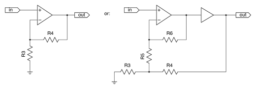
I Know What the Resistor Values Are. What’s the Gain?
This calculator takes an existing set of resistor values and
calculates the gain. It can do this for either a standard noninverting
op-amp gain stage (e.g. a CMoy pocket amp) or a Jung
multiloop gain stage, as in the schematics at right.
If you only give values for R3 and R4, it uses the simple gain
formula: G = R4÷R3 + 1. If you also give the R5 and R6 values,
it uses a formula derived by Headwize forum member Tophu.
By the way, another interesting derivation (due to SnoopyRocks this
thread) is
where Rg is R3 + R5, ƒo is the op-amp’s unity-gain bandwidth, and
ƒi is the desired inner loop bandwidth. 100 kHz is a useful starting
point for ƒi, but I don’t think there’s any hard-and-fast reason to
stick to this value. We’ve found that this gives too high a value for
R6 in the PPA for stability, if R5 is left at 3.32 kΩ. Just use it
as a starting point for investigating your own values, not as gospel.
If you are going to keep R3 and R5 at their default values for PPA and
PIMETA, and ƒi constant at 100 kHz, the expression can be approximated
as R6 = 0.043 * ƒo.
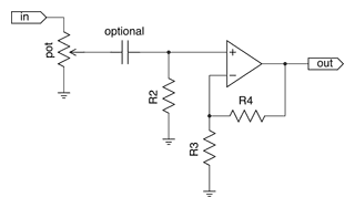
What Will the Output DC Offset Be?
This calculator estimates the output DC offset of a simple
noninverting op-amp gain stage, like the one at right.
The pot value is optional. If you leave it out, the calculator
assumes you have a cap in series between the pot and R2, so R2 sets
the +IN input impedance. Otherwise, this input impedance is calculated
as R2 and the pot in parallel over the pot’s range; the calculator uses
whichever value gives higher offset.
You have to give at least one of the datasheet values, but not
all of them. The calculator will happily give you a partial answer
if you just want to know the contribution of one source of offset.
The equation for the input current part of this calculator comes
from Design with Operational Amplifiers and Analog Integrated
Circuits 3rd edition by Sergio Franco. It is the modified form
of equation 5.11 on page 219. Using this calculator’s symbols, it
is:
where Rpf is value of the feedback resistors
R3 and R4 in parallel.
What Will the Noise Be?
This calculator estimates the output noise of a simple noninverting
op-amp gain stage like the one in the schematic at right.
This calculator assumes a typical audio application: bandwidth is
20 Hz to 20 kHz, and a full-scale signal is 1 Vrms. The
pot is assumed to be an audio taper pot, set at around the 80% level,
giving a 70/30 split on the resistance.
The calculator only considers Johnson noise from the resistors
surrounding the op-amp, plus the inherent voltage and current noise
specs of the op-amp itself. If you leave out the op-amp datasheet
specs, the calculator uses an ideal, noiseless op-amp. You can also
leave out R2 and the pot values, if you will not use these parts.
What is the Overall Resistance of Parallel Resistors?
What is the Reduction Factor of a Resistor Divider?
RI is the one between the divider’s input and the output,
and Rg is the one from output to ground.